High Frequency PCB and High Speed PCB Manufacturing Service
High-frequency PCB is a special PCB with a frequency range of 500MHz to 2GHz, widely used in applications involving specialr signal transmission between objects.
Home » PCB Manufacturing » High-frequency PCB
A special PCB
High Frequency PCB
Printed Circuit Boards are very high in demand because they make the circuit compact durable and ensure optimum performance with low errors and malfunctions. Nowadays, there are different types of PCBs available that can be used anywhere, even in a small flashlight or a large spacecraft. One of the special kinds of PCB is High-frequency PCB, which is used for special purposes. It has made a lot of things easier that were not possible to do using a normal PCB.
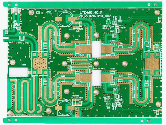
Table of Contents
What is High-Frequency PCB?
A high-frequency PCB refers to a special PCB that has a frequency range of 500MHz to 2GHz. This is a very high-frequency range that is not achievable in standard PCBs, which is why these PCBs are used for particular purposes where high-frequency signals are transmitted. High-frequency PCB is a circuit board produced on microwave substrate copper clad board using part of ordinary rigid circuit board manufacturing methods or using unique processing methods. Due to high frequency, communication and signal transmission are carried out at a faster rate. High-frequency PCBs’ primary use is in wireless communications, including satellites, telecommunication, and radar systems.
Why High-Frequency PCB?
When it comes to transmitting a signal at a higher frequency, there are many chances of losses, delays, and distortion in the signal. Thus, if we use a standard PCB for high-speed or high-frequency purposes, the results will not be optimum. The signals might get lost, or there could be huge losses after receiving the signal.
Furthermore, we cannot eliminate the use of high-frequency signals in the circuit because it’s the future. Nowadays, wireless transmission is widespread, and the best example is a Wi-Fi router working at your home. Some complex components and switches need signals faster, so the signal has a higher frequency. In simple words, high-frequency applications are increasing day by day because of the advantages that it offers. Thus, there is no choice to go for low-frequency signals to avoid the problem.
The only solution to these problems is the high-frequency PCB. A high-frequency is made of unique materials and has some specific features that allow it to transfer high-frequency signals with minimal loss. The High-frequency PCB is ideal for high-speed applications.
Materials for High-Frequency PCB
The materials that are used for high-frequency PCBs have unique qualities. If the material you have chosen is correct, it will offer the optimum results. Before you select any material, you need to go through some specifications to know whether the material is suitable for the application or not.
The important factors that you need to look at are,
- Dielectric Constant(DK)
- Dissipation Factor(DF)
- Coefficient of Thermal Expansion
- Moisture Absorption
Learn more about “PCB Materials“
Dielectric Constant(DK)
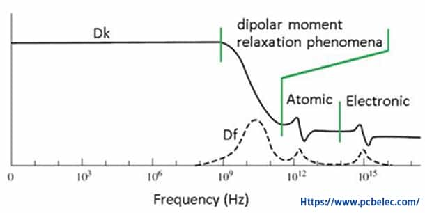
Dielectric constant (Dk) is also known as Relative Permittivity (Er). It is a crucial factor that should be considered while selecting the material for PCB, especially in high-frequency PCBs. When you read the value of dielectric contact of the material, it seems constant, and many people consider it a continuous value. In reality, it is a variable quantity that varies with the frequency. Typically, the value of the dielectric contact decreases with the increase in frequency. The dielectric constant of a high-frequency PCB should be small to prevent delays in signal transmission. Moreover, the constant value should remain stable for a wide range of frequencies to deliver the desired results.
Dissipation Factor(DF)
Dissipation factor (Df) is also termed as dielectric loss tangent. It is a significant factor in high-speed designs. It is the measure of signal loss during transmission. A low or no loss is desired in every case, including high-frequency applications. Df's value should be lower so that it cannot attenuate the signal or create a significant loss. The lower the dissipation factor, the better it is.
At higher frequencies, the loss is higher because the dielectric material absorbs more energy. Thus, if the high-frequency PCB materials are not picked wisely, there will be a loss of signals.
Coefficient of Thermal Expansion
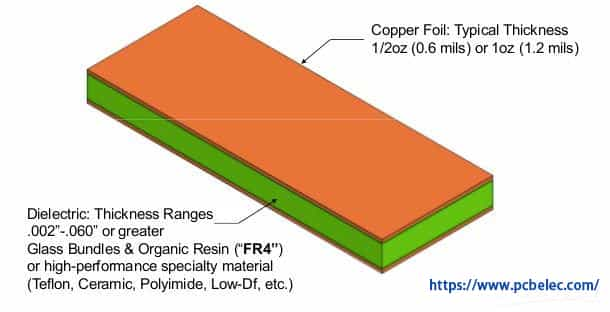
While selecting the material for a high-frequency PCB, thermal expansion's coefficient is an essential factor to look at. Above the base layer of the PCB, there is a copper layer, which is responsible for the conduction. If anything happens to that layer, the PCB will not work or provide the desired results.
The coefficient is analyzed wisely, and the material with the coefficient of a thermal expansion near to copper is selected. This ensures the expansion and contraction of the base material with the top copper layer. Otherwise, due to a massive difference in both the materials' coefficients, there can be a discontinuity in the electric connection. The top copper layer stays intact in a high-frequency PCB irrespective of the hot or cold temperature. Thus, the PCB can last for a long time and provide the desired results.
Moisture Absorption
The PCB material should not absorb too much moisture because it can increase the losses and delays in the transmission. If the humidity is absorbed too much, the dielectric constant and loss tangent is also affected.
Some Common High-frequency PCB Materials
By considering the above factors, some common materials that are used for high-frequency PCBs. Some of them are:
- High Performing FR-4
- PTFE
- Ceramic-filled PTFE
- Ceramic-fille Hydrocarbon
- E-fibre glas
Teflon is one of the best and most widely used materials for high-frequency PCBs. It can offer stable and optimum results. But it is more expensive as compared to FR-4. There are some popular and trusted manufacturers of high-frequency PCB materials; some of them are:
- Rogers (RO03001, RO03003, RO3010, RO4350B, RO4450B, RO4350 HF, RO4003)
- Isola IS620 E-fibre glass
- Isola FR408, FR 408 HR
- Isola IS 415
- Arlon 85N
- Taconic RF-35 Ceramic
- Taconic TLX
- GIL Taconic
- Nelco N4000-12/N4000-12SI
- Nelco N4000-13EP/N4000-13EPSI
- Nelco N8000
- Hitachi LX-67Y, FX II
- Getek
- Panasonic Megtron +
- Panasonic R2125
- Panasonic Megtron VI
The Cheapest and The Most Expensive High-Frequency PCB Material
The laminate cost of FR4, PPO, and Teflon, FR4 is the cheapest one, while Teflon is the most expensive one. In terms of DK, DF, water absorption, and frequency feature, Teflon is the best. When product applications require frequency above 10GHz, only can we choose Teflon PCB substrate to manufacture. Obviously, Teflon’s performance is far better than other substrates; however, the Teflon substrate has the disadvantage of high cost and large heat-resisting property. To improve PTFE stiffness and heat-resisting property function, many SiO2 or fiberglass as the filling material. On the other hand, due to molecule inertia of PTFE material, it is not easy to combine with copper foil; thus, it needs to do the special surface treatment on the combination side. Combined surface treatment normally uses chemical etching on PTFE surface or plasma etching to plus surface roughness or add one adhesive film between PTFE and copper foil. Still, these may influence dielectric performance.
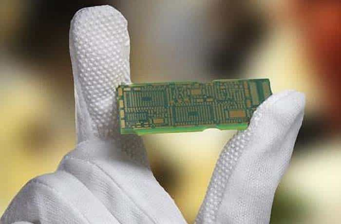
We manufacture high-frequency PCBs with frequencies typically in the range from 500MHz to 2GHz. The following table shows some of our common-use materials for High-Frequency PCBs manufacturing.
| Material | Dielectric Constant |
| RO4350B | 3.48±0.05@10 GHz |
| RO4003C | 3.38±@10 GHz |
| Ro3003 | 3.00±0.04@10 GHz |
| Ro3010 | 10.2±0.03@10 GHz |
| RT5880 | 2.20±0.02@10 GHz |
Several common high frequency circuit board material parameters
| Material for high frequency boards |  |  |  |  |  |  |  |  |  |
|---|---|---|---|---|---|---|---|---|---|
| °C | ppm/°C | @10GHz | KV/mm | MΩ | W/m*K | @10GHz | °C | N/mm | |
| Rogers 4350B HF material | 280° | 32 | 3,5 | 31 | 5,7 x 10^9 | 0,69 | 0,0037 | 390° | 0,9 |
| ISOLA IS620 E-fibre glas | 220° | 55 | 4,5* | – | 2,8 x 10^6 | – | 0,0080* | – | 1,2 |
| Taconic RF-35 Ceramic | 315° | 64 | 3,5** | – | 1,5 x 10^8 | 0,24 | 0,0018** | – | 1,8 |
| Taconic TLX PTFE | – | 135 | 2,5 | – | 1 x 10^7 | 0,19 | 0,0019 | – | 2,1 |
| Taconic TLC PTFE | – | 70 | 3,2 | – | 1 x 10^7 | 0,24 | – | – | 2,1 |
| Rogers RO3001 Bonding Film for PTFE | 160° | – | 2,3 | 98 | 1 x 10^9 | 0,22 | 0,0030 | – | 2,1 |
| Rogers RO3003 PTFE ceramic-filled | – | 25 | 3,0 | – | 1 x 10^7 | 0,50 | 0,0013 | 500° | 2,2 |
| Rogers RO3006 PTFE ceramic-filled | – | 24 | 6,2 | – | 1 x 10^5 | 0,79 | 0,0020 | 500° | 1,2 |
| Rogers RO3010 PTFE ceramic-filled | – | 16 | 10 | – | 1 x 10^5 | 0,95 | 0,0022 | 500° | 1,6 |
| ARLON 85N Polyimide HTg | 250° | 55 | 4,2* | 57 | 1,6 x 10^9 | 0,20 | 0,0100* | 387° | 1,2 |
PCB Materials Suppliers


Properties of High-Frequency PCB
The first and the most important property of high-frequency PCB is that it reduces the delay of signals. The material used to make the PCB has a very low dielectric constant (DK), which is why it works better for high frequencies. There are minimal delays and losses in the signals. The impedance remains in control.
No matter the temperature, the copper layer at the top of the PCB remains functional as it is supposed to be. It is because the coefficient of thermal expansion of copper is nearly equal to the base material, so they expand and contract together. Thus, there won’t be any discontinuity in the copper layer.
The glass transition temperature (Tg) of a high-frequency PCB is high, which means it can withstand high temperatures. It remains stable for a wide range of temperatures.
High-frequency PCB offers minimal attenuation of the signal. The reason behind this is the low dissipation factor (Df) of the base material. Due to minimal attenuation, the signal received at the receiver side is similar to the transmitter side. There is almost no decrease in the amplitude of the signal.
The materials used for high-frequency boards absorb very little moisture. Thus, the high-frequency signals are not affected by humidity. In contrast, standard PCBs can absorb moisture 25 times more than the high-frequency boards.
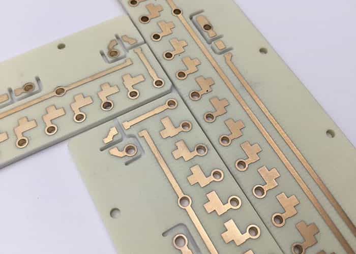
Applications of High-Frequency PCB
Telecommunications systems require a high-frequency signal transfer, which is the reason the devices contain a high-frequency PCB. The transmission of the signal in telecommunication is possible because of high-frequency, and any loss or attenuation in the signal can be problematic. Thus, a special high-frequency board is necessary.
Radars also have an antenna that is responsible for receiving a high-frequency signal without wires. It is only achieved using the high-frequency PCB.
Satellites also require high-frequency communication. High-frequency PCBs are widely used in satellites.
We use several wireless devices at our homes and other places. This includes Wi-Fi routers, remote controllers, cell phones, GPS receivers, and RF IDs. Thus, high-frequency PCB is also common in our daily life.
For high-speed switching, a higher frequency is required. For instance, if you are using a high-speed switching transistor, you need a high-speed frequency signal. Such a signal can only be transmitted using high-frequency PCBs. High-speed switching is common in power devices and solar converters/inverters.
Many modern medical types of machinery use high frequencies, including the ultrasound machine, X-ray, and MRI scanners.
Military applications also require high-frequency PCB for communications in missile operation and other warfare machines that require wireless communication.
Factors influencing a high frequency PCB Design
Some of the factors needed to design high frequency PCB are mentioned below:
- The selection of PCB material for high-speed digital circuits is influenced by several factors. The high frequency PCB must offer following features apart from a good structural build-up. Impedance controlled multilayers
- Sandwich buildup for material combinations
- Controlled production line
- Signal loss tolerance
- Heat sinking ability
- Operating temperature(temperature expansion, stability over a temperature range)
- Production cost
High Frequency PCB Products
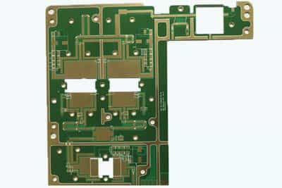
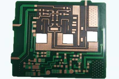
2 Layer High Frequency Microwave PCB
- Thickness: 0.8 + / – 0.1 mm
- Material: rogers4350
- Dielectric constant: 3.48±0.05
- Dielectric loss factor: 0.0037
- Minimum aperture: 0.3mm
- Surface treatment: Immersion Gold
- Minimum line width/distance: 0.2mm/0.25mm
- Process features: special material, fill with ceramic material
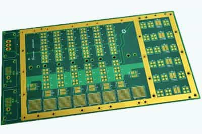
4 Layer High Frequency Microwave PCB
- Thickness: 1.6±0.14 mm
- Material: rogers5880+SHENGYI FR4
- Dielectric constant: 2.2±0.02
- Dielectric loss factor: 0.0009
- Minimum aperture: 0.3mm
- Surface treatment: OSP
- Minimum line width/distance: 0.2mm/0.3mm
- Process features: special material, Rogers5880+SHENGYI Fr4 Hybrid Laminate
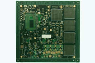
22 Layer High Frequency PCB
- Thickness: 4.0±0.2 mm
- Material: SHENGYI
- Dielectric constant: 4.2±0.05
- Dielectric loss factor: 0.0007
- Minimum aperture: 0.4mm
- Surface treatment: Immersion Gold
- Minimum line width/distance: 0.33mm/0.2mm
- Process features: Multilayer, Super-thick Board
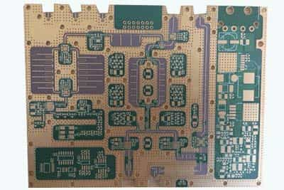
12 Layer High Frequency Microwave PCB
- Thickness: 2.0 + / – 0.14 mm
Material: SHENGYI FR4 - Minimum aperture: 0.2mm
- Surface treatment: Immersion Gold
- Minimum line width/distance: 0.15mm/0.13mm
- Process features: hole to line spacing 0.2mm, BGA size 0.2mm
Teflon High Frequency Microwave PCB
- Thickness: 1.6 + / – 0.1 mm
- Dielectric constant: 2.65±0.05
- Dielectric loss factor: 0.0037
- Minimum aperture: 0.3mm
- Surface treatment: Immersion Gold
- Minimum line width/distance: 0.2mm/0.25mm
- Process features: special material, Fill with ceramic material
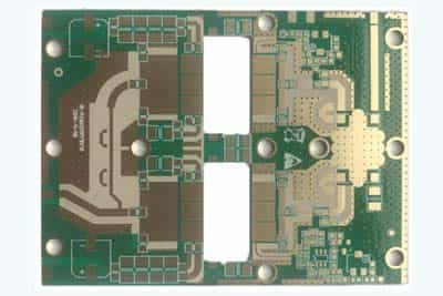
Double Layer High Frequency PCB
- Thickness: 0.8±0.1mm
- Material: RF-35
- Dielectric constant: 3.5±0.05
- Dielectric loss factor: 0.0037
- Minimum aperture: 0.3mm
- Surface treatment: Immersion Gold
- Minimum line width/distance: 0.35mm/0.2mm
- Process features: Taconic high frequency materials
Recommended PCB manufacturing services
Get Your High-Frequency PCB Today!
JHYPCB is a large manufacturer of all kinds of PCBs and PCB assemblies, from small to large volumes. We are ISO, UL, and RoHS certified and compliant manufacturers. Our strict quality management system ensures high-quality PCBs. We also offer high-frequency PCBs of your choice. We provide complete full turnkey PCB assembly services and fast prototype services. For more information and details, feel free to contact us.
